
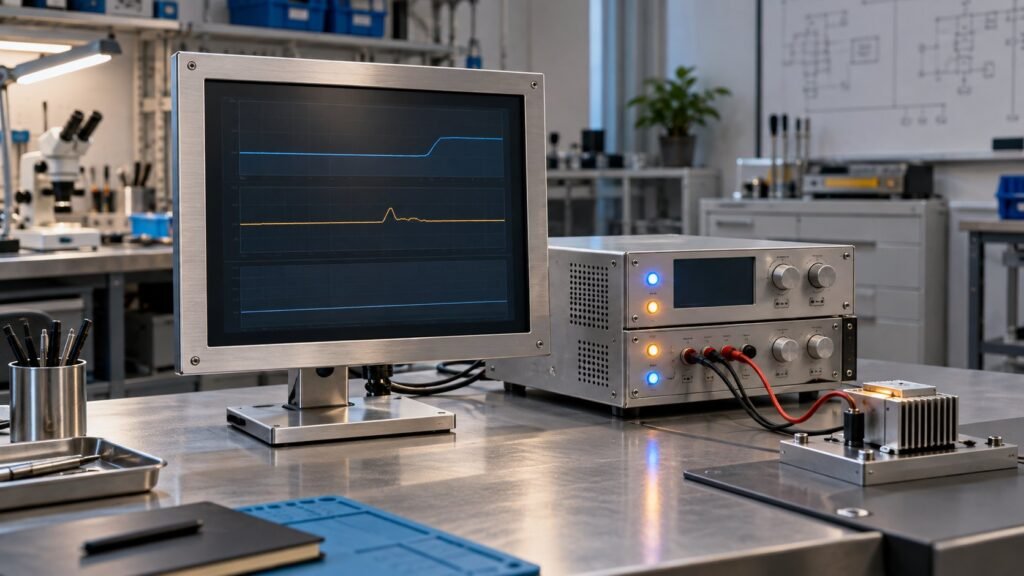
A 19 industrial monitor 24V input should be accepted on measured dip behaviour, not its 9–36V label alone. Test startup at 9, 12, 18, 24 and 36V, record steady current and power, then pull the 24V rail below 18V. Pass only if the display avoids black-screen loss or reboot and recovers within your limit.
The reason to tighten this test now is IEC 61000-4-29:2026, published on 30 July 2026. Ashkan, IronView industrial monitor engineer, translates that DC-input immunity revision into a repeatable acceptance check for your 17.3-inch, 18.5-inch and 19-inch monitor installations.
What changed in IEC 61000-4-29:2026?
IEC 61000-4-29:2026 defines repeatable tests for DC-input voltage dips, short interruptions and voltage variations. It also specifies test levels, generator requirements, setup and procedure. Use Clause 5 to identify severity levels and Clause 6 to check generator limits before you compare test results.
The IEC publication page describes the 2026 edition and its tracked changes from the previous publication. The standard gives you a test framework. It does not turn a wide input label into a guaranteed pass threshold. Your purchase specification still needs a dip depth, duration, source impedance, recovery limit and visible-failure rule.
Why does a nominal 24V rail brown out?
A 24VDC monitor can lose its image when another device changes the shared rail faster than the supply wiring can respond. Lilliput’s Industrial Touch Screen Monitor Buyer’s Guide identifies PLCs, sensors and larger switched loads as common causes of rail sags or spikes.
The monitor terminals see the result, not the nominal output printed on the power supply. Cable resistance, shared return paths and solenoid inrush can create a short notch below the monitor’s practical operating limit. A broad DC input voltage range improves margin, but it does not prove voltage dip immunity for your waveform.
- PLC or sensor switching changes the shared load current.
- A solenoid or contactor creates a fast current step.
- Long or undersized conductors increase the voltage drop at the monitor.
- The display controller may reset before the backlight visibly fails.
- A reboot can interrupt the operator view even after the rail returns to 24V.
See also: Rack Mount Industrial Monitor Fit Checklist
What does a 19 industrial monitor 24V input claim prove?
A published input range proves the stated operating envelope under the manufacturer’s conditions. It does not state the voltage-dip threshold, recovery time, test severity or failure trigger. The live 19-inch product pages from Teguar and Touch Think show why you need a second acceptance layer.
| Model or source | Published DC claim | Use when | Still required for acceptance |
|---|---|---|---|
| Teguar TD-45-19 | DC 9–36V | Your rail can move across a wide steady-state range | Dip depth, duration, recovery and black-screen result |
| Touch Think TPC190-M41 | DC 9–36V; parameter table lists 12–24V | You need to reconcile the headline range with the parameter table | Clarification of the applicable rating and a rail-event test |
| IronView IV19-PM-24 | Bench results recorded at 9, 12, 18, 24 and 36V | You need measured startup, load and brownout data | Repeat the test in your enclosure and with your switched loads |
Teguar’s TD-45-19 page lists DC 9–36V. Touch Think’s TPC190-M41 page lists DC 9–36V and also shows 12–24V in its parameter table. Treat both as selection data, not as proof that the screen will survive the transient created by your control cabinet.
See also: 19 industrial monitor
What did IronView measure on its 19-inch unit?
IronView tested the IV19-PM-24 19-inch panel-mount monitor with a regulated DC source and logging at the monitor terminals. The controlled hold-up test used a 100 ms voltage reduction and a 1 V/ms ramp. Recovery time is the interval from restored nominal voltage to a stable displayed image.
| Applied voltage | Startup voltage | Steady current | Power | Minimum hold-up voltage | Recovery time | Result |
|---|---|---|---|---|---|---|
| 9V | 9.0V | 1.47A | 13.2W | 8.4V | 510ms | Started and recovered |
| 12V | 12.0V | 1.13A | 13.6W | 10.6V | 360ms | Started and recovered |
| 18V | 18.0V | 0.82A | 14.8W | 16.8V | 230ms | Started and recovered |
| 24V | 24.0V | 0.64A | 15.4W | 17.2V | 190ms | Started and recovered |
| 36V | 36.0V | 0.46A | 16.6W | 17.4V | 170ms | Started and recovered |
The installation trigger was different from the controlled ramp. At 24V nominal, energising a 24V solenoid pulled the IV19-PM-24 rail to 17.6V for 120 microseconds across three repeated notches. The display black-screened and rebooted in 1,840ms in five of five trials. The measured failure threshold was below 18V during that fast event.
That result is why you should specify the waveform, not only the minimum DC input. The unit held a slower controlled dip to 17.2V, yet the sharper shared-rail event caused failure. IronView’s project acceptance limit for this test is no visible image loss at 18.0V for 100ms and recovery below 500ms.
How should you run the acceptance test?
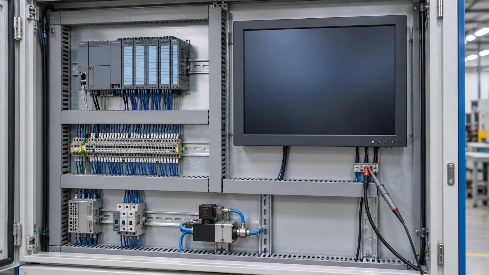
Run the test at the monitor terminals with the final cable length, return path and switched loads installed. Record both voltage and current. A bench-only result is incomplete if the enclosure wiring creates the actual disturbance.
- Set the DC source to 24V and connect the final harness. Failure mode: an unmeasured voltage drop between the supply and monitor hides the real trigger.
- Start the monitor at 9V, 12V, 18V, 24V and 36V. Record startup voltage, steady current and power. Failure mode: no boot, unstable image or abnormal current at any required point.
- Apply the agreed dip profile using the severity level from Clause 5 of IEC 61000-4-29:2026. Failure mode: black screen, touch-controller loss or reboot during the dip.
- Verify the generator limits and waveform setup against Clause 6. Failure mode: a result that cannot be reproduced because the source impedance, rise time or output capability is uncontrolled.
- Switch the real solenoid, contactor or motor load on the shared 24V rail. Failure mode: the rail falls below 18V and the monitor loses its image or restarts.
- Restore nominal voltage and time recovery to a stable image. Failure mode: recovery exceeds 500ms, leaves artefacts or requires operator intervention.
Keep the oscilloscope probe at the monitor input connector. Logging only at the power supply can miss a short local notch. Record the event voltage, duration, load current and display response in the same test file.
FAQ: 19-inch monitor DC input testing
Is 9–36V enough for a 24V installation?
No. It confirms a steady-state input range. You still need a controlled dip test and a switched-load test at the monitor terminals.
Why does a product page show both 9–36V and 12–24V?
The two figures may describe different sections of the specification. Treat the narrower parameter-table figure as an open question until the manufacturer confirms which condition applies.
What should your voltage dip requirement include?
Specify nominal voltage, dip level, duration, waveform, source impedance, load event, visible-failure rule and recovery limit. Without those fields, two suppliers can claim compliance against different tests.
What should you specify before buying?
Specify the monitor’s steady DC input range and its tested dip behaviour as separate requirements. Use the Industrial Monitor Spec Glossary for input terminology, compare the installation context in IronView applications, and ask for the exact test record before you approve a 19-inch unit. To review your rail profile and request a 19-inch monitor acceptance plan →


