Fanless industrial display monitors reduce forced-air failure modes by removing fan-bearing wear and dust ingestion, but they do not remove thermal risk. Above 60 °C, the LCD stack can become the bottleneck. Prove the design at 25 °C, 45 °C and 60 °C ambient by measuring chassis, LCD-surface and driver-board temperatures, warm-up time, and luminance or contrast change.
Fanless panel-PC guides often stop at headline temperature ranges. They do not show standalone monitor measurements or the LCD-specific trigger that ends a test. Ashkan, IronView industrial monitor engineer, uses the three-point map below to separate a published specification from thermal evidence.
Why do fanless industrial display monitors still need thermal proof?
Fanless construction removes a recurring forced-air failure path; it does not guarantee a cool LCD stack. The useful question is where heat accumulates at the panel surface, driver board and chassis across the industrial display operating temperature.
Rugged Panel PC HMI Specs: Fanless, IP65, SSD, Temperature identifies fan-bearing wear and dust ingestion as forced-air failure modes. The same guide warns that the LCD stack can become the thermal bottleneck above 60 °C. That changes the test priority: measure the display layers, not only the enclosure exterior.
Ankh Innovations describes conduction cooling to 55 °C ambient and calls fan failure a common field problem. Its example supports the value of a fanless industrial monitor, but 55 °C conduction cooling is not proof that every LCD remains within its optical limits. Your industrial monitor thermal design still needs measured surface temperatures and output checks.
See also: Loading Rack Monitors: Specifying the Gantry Display
Which IronView SKUs should you compare?
The current IronView BOM comparison covers IM-173, IM-185 and IM-19S. The published baseline for these models is fanless construction, a −20…60 °C operating range and 50,000-hour panel MTBF. Treat that baseline as the starting specification, not as a completed thermal qualification.
| BOM SKU | Size | Published baseline | Use when |
|---|---|---|---|
| IM-173 | 17.3″ | Fanless; −20…60 °C; 50,000-hour panel MTBF | Your brief needs a 17.3-inch standalone display |
| IM-185 | 18.5″ | Fanless; −20…60 °C; 50,000-hour panel MTBF | Your control position suits an 18.5-inch screen |
| IM-19S | 19″ | Fanless; −20…60 °C; 50,000-hour panel MTBF | Your installation requires the 19-inch 5:4 format |
Industrial Monitors | Rack, Open Frame & Panel Mount lists fanless design, −20…60 °C operation and 50,000-hour panel MTBF for the IronView range. A panel MTBF is a life estimate. It does not show whether the LCD surface reaches an optical failure limit during a hot start or sustained load.
See also: How to Choose a SCADA / Control Room Display
How should you run the three-point thermal map?
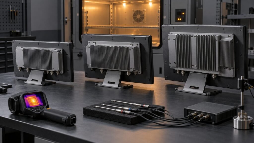
Run each SKU at 25 °C, 45 °C and 60 °C ambient until the readings stabilise. At every point, record the chassis hotspot, LCD-surface temperature, driver-board temperature, warm-up time and measured luminance or contrast change.
- Establish a 25 °C baseline after cold start. Record luminance in cd/m² or contrast ratio, then note the time in minutes required to reach stable output. Failure mode: an incorrect baseline hides later contrast loss.
- Repeat at 45 °C ambient with the same input signal, brightness setting and measurement locations. Record the hottest chassis point and driver-board temperature. Failure mode: a local hotspot can exceed the average enclosure temperature.
- Repeat at 60 °C ambient and continue until the thermal readings plateau or the unit fails. Record LCD-surface temperature separately from chassis temperature. Failure mode: the LCD stack may reach its limit before the electronics shut down.
- Compare luminance or contrast with the 25 °C baseline. Report the absolute value and percentage change. Failure mode: contrast collapse can make the image unusable while the monitor still appears powered.
- Record thermal shutdowns, blackouts, image dropouts and recovery behaviour. Failure mode: an intermittent blackout may disappear after cooling and remain absent from a simple pass/fail check.
Use the same probe type, contact method, signal pattern and warm-up definition across IM-173, IM-185 and IM-19S. Without those controls, a comparison between sizes is anecdotal. The report should show whether the 60 °C rating remains usable at the LCD surface, not merely whether the monitor continues drawing power.
How should vibration qualification be reported?
Use IEC 60068-2-6:2007 Test Fc and state the selected vibration severity, rather than writing only “vibration tested”. Severity should include the frequency range in Hz, displacement in mm peak-to-peak or acceleration in m/s² or g, sweep rate in octaves per minute, number of sweeps or duration, test axes and mounting orientation.
If qualification testing exists, the Clause 13 report should identify the SKU, hardware revision and serial numbers; fixture and mounting method; selected severity; axis sequence; pre-test conditioning; powered or unpowered state; live image monitoring; pre-test and post-test results; and every observed failure. Record driver-board resets, blackouts, image artefacts and contrast changes as functional results.
- State the exact Test Fc severity and sweep profile.
- Identify the test fixture, orientation and restrained points.
- Record whether the display operated during each axis.
- Log thermal or optical changes before and after vibration.
- Name any failed component or repeat test condition.
IEC 60068-2-6:2007 is a test method, not a single universal severity. Your supplier must publish the selected severity and the Clause 13 evidence for the actual qualification configuration.
Fanless industrial monitor questions to ask before approval
Does fanless mean there is no thermal risk?
No. Fanless removes fan-bearing wear and dust ingestion, but heat still moves through the chassis, driver board and LCD stack. Above 60 °C, the LCD can become the limiting component.
What evidence should a supplier provide?
Request the SKU, published operating range, panel MTBF, three-point thermal map, warm-up time, luminance or contrast change, and any IEC 60068-2-6:2007 Test Fc report.
Why measure the LCD surface separately?
The chassis can remain within its average temperature while the LCD stack reaches a local limit. Surface temperature and optical output reveal contrast collapse before a full thermal shutdown.
What should you approve?
Approve a fanless monitor only when the SKU, −20…60 °C range and 50,000-hour panel MTBF are backed by the 25 °C, 45 °C and 60 °C thermal map. Compare the panel-mount monitor range, then use the Industrial Monitor Spec Glossary to check every thermal field →