
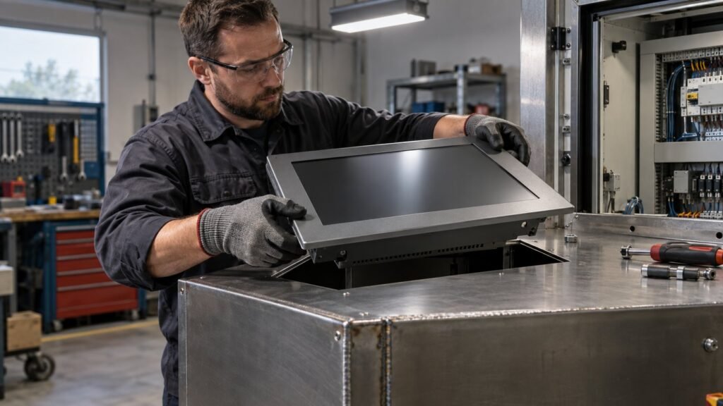
Einbau monitore mit frontplatte — mounting a panel monitor through a front-plate cutout — comes down to three things: a cutout cut to the right tolerance, a gasket compressed evenly across its full perimeter, and clips torqued in the correct pattern. Get one of these wrong and you lose the IP rating you specified, even if every component on the bill of materials is correct.
This guide assumes you’ve already chosen panel mount over open frame and settled on an IP target. It covers the fabrication steps our integrators ask about most: cutout dimensions for IronView’s 17.3″, 18.5″ and 19″ industrial monitors, the panel flatness spec that decides whether the compression gasket actually seals, and the torque sequence that seats a bezel without cracking it.
Cutting the Front-Plate Cutout
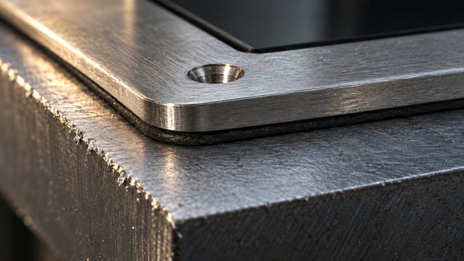
Rockwell Automation’s installation instructions for its industrial standard monitors state the cutout must be cut slightly smaller than the monitor’s bezel, so the mounting flanges overlap the panel surface on all four sides. That overlap is what holds the gasket under compression. Undersize the cutout and the flanges won’t seat flush; oversize it and you lose sealing contact at the corners — the first place a rating fails under a hose-down test.
The front plate itself has to be rigid enough to carry that overlap without flexing. A thin, unsupported panel around a panel mount monitor front plate cutout will bow under gasket pressure and open a leak path along one edge, usually the longest one. Where the panel is thin steel or unbraced aluminium, add a stiffening frame behind the cutout before you cut, not after.
Cutout Size Scales With Screen Diagonal
Cutout dimensions aren’t a fixed ratio of screen diagonal — they follow each manufacturer’s own bezel design. Hope Industrial Systems lists a cutout of roughly 528.7mm x 342.3mm for its 22″ widescreen panel mount monitor and touch screen. That figure is a useful cross-check if you’re speccing openings across a mixed-brand fleet, but never substitute one vendor’s numbers for another’s cutout drawing — bezel step height and flange width differ enough to matter at the corners.
See also: Open Frame Einbau Monitore: Montage-Leitfaden
Einbau Monitore mit Frontplatte: Cutout Dimensions by Screen Size
We publish cutout drawings for every model in the IronView range, toleranced to +0.5mm/-0.0mm on width and height. That one-sided tolerance matters: a cutout cut oversize by even 0.5mm on two edges can drop flange overlap below the minimum needed for gasket contact. Current figures for our industrial panel mount monitors:
- 17.3″ panel mount monitor — cutout 409.0mm x 250.0mm, panel thickness 1.5mm–6.0mm, minimum rear clearance 45mm.
- 18.5″ panel mount monitor — cutout 432.0mm x 267.0mm, panel thickness 1.5mm–6.0mm, minimum rear clearance 48mm.
- 19 panel mount monitor — cutout 386.0mm x 309.0mm on a 5:4 bezel, panel thickness 1.5mm–6.0mm, minimum rear clearance 50mm.
Rear clearance isn’t decorative — it’s the space needed behind the panel for connector strain relief and convection cooling once the enclosure door closes. Cut it tight and you’ll fight cable dress on every unit that comes off the line. On mixed panel-thickness runs, always spec the cutout to the thickest panel in the batch; a cutout sized for 1.5mm steel will under-clamp on 6mm steel even inside the stated tolerance.
Panel Flatness and Gasket Compression
Rockwell Automation specifies panel flatness within 0.2mm across the sealing area for its compression gaskets — beyond that, the gasket can’t close the gap uniformly and the IP rating is compromised, regardless of how well the cutout was cut. In our install reviews, the single biggest cause of gasket failure isn’t a bad gasket — it’s a panel that’s flat on paper but not flat in practice. Powder-coated doors with a slight crown from welding heat, or laser-cut panels with dish distortion near the cutout, both fail this way.
We’ve traced two field returns this year to exactly that pattern: the gasket sealed on three sides and left a hairline gap on the fourth, invisible on the bench and only found once the enclosure failed a hose-down test. If you’re fitting front IP rated industrial displays into anything with a welded or formed panel, check flatness with a straightedge and feeler gauge before you mount — don’t trust the cutout alone.
Prepping Painted Panels
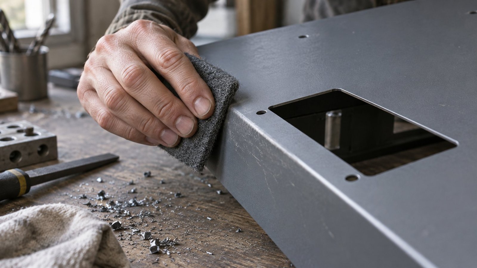
Rockwell Automation’s instructions also cover painted panels specifically: scuff the sealing area with 320-grit abrasive and clean it with isopropyl alcohol before the gasket seats. Paint film is soft and uneven at a microscopic level — the gasket compresses into it unevenly unless the surface is broken up first. Skip this step and you’re relying on paint thickness to hold a seal it was never rated for.
See also: Rugged Touch Screen Monitor Gloves Test
Torquing the Mounting Clips in a Cross Pattern
Clips go on in a cross pattern — opposite corners first, then the remaining pair — tightened to 8 inch-pounds. Stop when the bezel just contacts the enclosure surface. Never judge this by feel; hand-tightening alone under- or over-compresses the gasket depending on who’s holding the driver, and both directions cost you sealing performance.
- Set a torque driver or torque screwdriver to 8 inch-pounds.
- Tighten the clip at one corner until the bezel just touches the panel — no more.
- Move to the diagonally opposite corner and repeat.
- Tighten the remaining two corners in the same diagonal order.
- Run a second pass around all four clips to catch any settling as the gasket compresses.
FAQ: Installing Panel Mount Monitors Through a Front Plate
How much smaller should the cutout be than the bezel?
Enough for the mounting flange to overlap the panel on all four sides — for IronView units, that’s built into the +0.5mm/-0.0mm cutout tolerance on our drawings. Follow the drawing for your model rather than estimating an offset by eye.
Can I reuse an existing cutout from an older install?
Only if the cutout dimensions match your new monitor’s drawing exactly. Bezel step height and flange width vary between models and manufacturers, so a cutout sized for one unit rarely seals correctly on another, even at the same nominal screen size.
What torque wrench should I use for the clips?
A calibrated inch-pound torque driver set to 8 inch-pounds, preset if you’re running multiple units on a line. A click-type driver stops you overtightening past the point the bezel contacts the enclosure.
Does panel paint or coating affect the seal?
Yes. Scuff the sealing area with 320-grit abrasive and wipe it with isopropyl alcohol before mounting, per Rockwell Automation’s installation instructions. Uncleaned or unscuffed paint is a common cause of uneven gasket compression.
Choose the Right Panel Mount Monitor for Your Install
Cutout drawings, flatness checks and torque sequence only work if the monitor behind them is speced correctly for the enclosure in the first place. Browse IronView’s panel mount monitors for cutout dimensions, gasket specifications and IP ratings across the 17.3″, 18.5″ and 19″ range, or send your panel drawing to Contact & Quotes for a fit check before you cut steel. →


